|

 
| |
Perform a Manual IPL
*IMPORTANT
Prior to performing an IPL you MUST shut down the
internal network server.
- WRKCFGSTS *NWS
- Option 2 = stop (Option 1 = start)
Front Panel System Shut Down (IPL)
- 01 BN
- Up arrow to
02
-
ENTER
- Up/down arrow to
02 BM
-
ENTER
- Press the
white power button
- When
0? appears
press the
white power button again
|
Front Panel Operationforce a manual IPL.
To select manual IPL:
From front panel, select 02, Enter then up or down to B M and
Enter
To force IPL:
Select 03, Enter for start IPL
|
| |
| IBM Web Information
Document Title
Front Panel Functionality
Document Description
Front Panel Operations and
Keylock positions.
The IBM® iSeries™ family of servers front panel
comes in many flavors and has varied a lot in the functionality of
the controls and their layout over the lifetime of the product
family. This document is a quick guide to the Control Panel.
On all iSeries family servers, the vast majority
of front panel functions are disabled if the system is powered up
and running in N
(normal) mode.
Below are diagrams of the panels and lists of the
functions that they perform.
 CISC
Systems: Models Axx through Fxx and 1xx through 3xx CISC
Systems: Models Axx through Fxx and 1xx through 3xx
CISC Systems: Models Axx
through Fxx and 1xx through 3xx
System Unit Control Panels
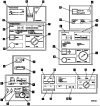
Picture 1 below is an example of the generic
control panels in use for the CISC model systems contained in
White/Beige
cabinets.
| o |
The upper left panel
is for the 9406 Bxx through Fxx model systems.
|
| o |
The upper right is
the 9404 Bxx through Fxx model systems. |
| o |
The lower right panel
is for the 1xx and Axx through Fxx model systems. |
| o |
The lower left is for
9404 1xx models. |
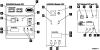
Picture 2 is an example of the control panels for
the CISC systems (models 3xx and 2xx) which are contained in
Black boxes.
A
Power On
The light comes on when there is power to the
system unit.
Note:
The Power On light blinks when the system is
being started up and when the system is manually turned off. When
the Power Down System (PWRDWNSYS)
command or the options on the Power On and Off Tasks (POWER) menu
are used, the Power On light does not blink.
B
Power Switch or Push-button
For the 9402 Models 1xx and Axx-Fxx, there are
two separate switches for Power On and Delayed Off. Press the Power
On switch to start the system or the Delayed Off switch to stop the
system.
For the 9401 Models P0x and 10x, 9404 Models 1xx,
9402/9404 Models 2xx, and 9404/9406 Models 3xx, the power switch is
a push-button. For the 9401 Models P0x and 10x, 9404 Models 1xx,
press the push-button to start the system; press it again twice to
stop the system, the first push will display
0? which is a
fail-safe that means, do you really
want to do this?.
For the 9404 Models Bxx-Fxx and 9406 Models
Bxx-Fxx System Units, the manual Power switch can be moved to the
Power On (top) position to start the system or the Delayed Off
(bottom) position to stop the system. When you move the Power switch
to either the Power On or Delayed Off position and remove your hand
from the switch, the switch returns to the center position.
C
Processor Active
On the 9406 Models Bxx-Fxx,
9401 Models 1xx, and some 9404/9406
Models 3xx System Units, the Processor lights provide a graphical
display of the processor activity. On the other iSeries family
server units, the Processor Active light blinks when programs are
running.
D
System Attention
This light comes on when the system requires
operator attention, such as correcting a severe system failure.
E
Function Display
The Function display shows the function
information that has been entered. The left two positions indicate
the number that is selected using the Select switch.
Function/Data Display
The 9401 Models P0x and 10x, 9402 Models 1xx and
Axx-Fxx, 9402/9404 Models 2xx, and 9404/9406 Models 3xx have only
one display for both function and data. When you press the Select
switch or push-button (increment or decrement), the function number
appears in the Function/Data display. When you press the Enter
push-button, the function number disappears, and the data is shown
for the previously displayed function. Only the numbers of those
functions that can be used in the present mode are displayed. The
Function/Data display for these system units can display up to eight
digits. The selected function is not sent to the processing unit
until the Enter push-button is pressed. The system reference codes
or other information from the processing unit or control panel are
also shown in the Function/Data display.
F
Data Display
The 9404 Models 1xx, 9404 Models Bxx-Fxx, and
9406 Models Bxx-Fxx Data displays can show up to eight digits for
system reference codes or other information from the processing unit
or the control panel. The Data display clears whenever the Select
switch or push-button (increment or decrement) is pressed or a
different function is shown on the Function display. When you press
the Enter push-button, the Data display can again display data.
G
Select Switch or Select Push-Button
The Select switch or push-button (increment or
decrement) can be used to increase or decrease the number shown in
the Function display. The Select switch or push-button (increment or
decrement) can also be used to change the data shown in the Data
display when you are selecting an Initial Program Load (IPL) type.
For the 9406 Models Bxx-Fxx and 9404 Models
Bxx-Fxx System Units, the numbers in the Function display decrease
in value when you press the lower portion of the Select switch.
Similarly, when you press the upper portion of the Select switch,
the numbers in the Function display increase in value.
When the Function display has reached its maximum
number and the upper portion of the Select switch is pressed again,
the next number shown is the minimum number. Similarly, when the
Function display has reached its minimum number and the lower
portion of the Select switch is pressed again, the next number shown
is the maximum number.
There are two Select push-buttons for the 9401
Models P0x and 10x, 9404 Models 1xx, 9402/9404 Models 2xx, and
9404/9406 Models 3xx. The increment push-button increases the values
in the Function display, and the decrement push-button decreases the
values.
For the 9402 Models 1xx and Axx-Fxx, there is
only one select push-button. The number on the Function/Data display
increases in value when you press the select push-button, until it
reaches the maximum value. If you press the Select push-button
again, the next number shown is the minimum number.
H
Enter Push-Button
The Enter push-button is used to send function
information shown in the Function display to the processing unit or
to save the type of IPL you selected.
J
Mode
On most of the iSeries family server units, there
are four modes available: Manual, Normal, Auto, and Secure. For the
9402/9404 Models 2xx and 9401 Models P0x and 10x, only Manual and
Normal modes are available.
To select the mode for the 9402/9404 Models 2xx
and 9401 Models P0x and 10x, do the following:
| 1 |
Use the Select
push-button (increment or decrement) to select Function 02,
and press the Enter push-button. |
| 2 |
Use the Select
push-button (increment or decrement) to select the IPL type
and mode. Since Function 02 can also be used to select IPL
type, the Function/Data display for the 9402/9404 Models 2xx
or 9401 Models P0x and 10x shows both IPL type and mode at
the same time. |
 RISC
Systems: Models Sxx, 1xx, 2xx, and 4xx through 8xx RISC
Systems: Models Sxx, 1xx, 2xx, and 4xx through 8xx
Mode
Descriptions
Mode Descriptions
The following table summarizes the tasks you can
perform in the Manual, Normal, Auto, or Secure modes:
|
|
|
|
|
|
Turn on System
(Power push-button)
|
|
|
|
|
Power off
(Power push-button)
|
|
|
|
|
|
|
|
|
|
|
|
|
|
|
|
|
|
|
|
|
|
|
Display system reference code
|
|
|
|
|
|
|
|
|
|
|
|
|
|
|
|
|
Restart IPL (IPL after power failure)
|
|
|
|
|
Power down system command
|
|
|
|
|
1
Allowed for some models
|
 |
|
|
Manual
When the mode is set to Manual, the system allows
you to do all manual IPLs, such as an operator-attended IPL from
disk or tape, and manual control functions, such as select an IPL or
display the kind of IPL that the system is set to run. However, you
cannot do a remote IPL, an IPL by date and time, or an IPL after a
power failure.
Note:
You should only set the mode to Manual when necessary. This will
ensure that no one accidentally presses the Power push-button and
causes the system to stop.
Normal
The Normal mode allows you to manually turn the
power on and to do each of the automatic operations. That is, you
can start the system by doing a manual or remote IPL, an IPL by date
and time, or an IPL after a power failure.
If you want to stop the system when the mode is
set to Normal, use the Power Down System (PWRDWNSYS)
command at any display station. You must have QSYSOPR authority to
use the Power Down System (PWRDWNSYS)
command.
Attention: If your system has
logical partitions, using the Power push-button,
DST
option 7, or the Power Down System
(PWRDWNSYS)
command can affect multiple partitions. For details on using
logical partitions on your iSeries family server, go to
Managing logical partitions under the Logical Partitions
topic in the iSeries Information Center. |
Auto
The Auto (automatic) mode allows a remote IPL, an
IPL by date and time, and an IPL after a power failure.
When the mode is set to Auto, you cannot do the
following:
| o |
Start the system by doing
an IPL manually. |
| o |
Stop the system by using
the Power push-button. |
| o |
Select a different IPL
type by using the Increment/Decrement buttons. |
For more information about the types of IPLs, see
Starting and Stopping the System
in the Basic System
Operation, Administration, and Problem Handling
manual (SC41-5206-xx, where xx is the current version of the
manual).
Secure
The Secure mode locks the control panel on the
system unit. You can only stop the system from a display station by
using the Power Down System (PWRDWNSYS)
command.
|
|